IPS Rocket Removal
100168-03
Use the following procedure to remove the rocket installation.
Applicable Aircraft Serial Numbers
All
Type of Maintenance
Line
Level of Certification
LSA-RM
Task Specific Training Required
Yes, contact ICON for rocket-specific training prior to performing any rocket-related portion of this task.
Special Tools Required
None
Parts Required
None
Aircraft System and Number
16—ICON Parachute System (IPS)
Safety Equipment
As Needed
Consumables
None
Warning:
Do not “experiment” with the BRS Recovery System or fire it on the ground just to see if it works. People may be injured, property damaged, and thousands of dollars of expense will be incurred to repack the parachute and recharge the rocket. In addition, firing the BRS Recovery System experimentally will render it and the aircraft unusable until the factory has serviced it. Treat the BRS Recovery System like a loaded gun. Verify the “REMOVE BEFORE FLIGHT” pin is installed.
Task Instructions
2. Install the detent pin with “REMOVE BEFORE FLIGHT” flag into the activation handle before proceeding.
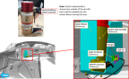
3. Remove the Cone Adapter from Rocket Attach Cone (Figure 555). It may be necessary to use rubber channel locks to break the Adapter loose.
Figure 553. Rocket Mount Installation

Figure 554. Rocket Mount Nuts Inside the Firewall
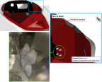
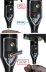
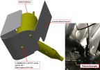
4. Remove the Pull Cable Screw Cover (Figure 555) and unscrew the screw retaining the Pull Cable from the Igniter Plunger (Figure 556). A magnetic tip driver will help prevent dropping the screw.
Note:
Ensure star washer is removed with screw.
Figure 555. Rocket Attach Cone and Cone Adapter

Figure 556. Reference Image, Cone Cutaway for Clarity. Connection of Rocket Pull Cable to the Igniter Plunger
5. Slowly pull cable from rocket attach cone. Cable should take little to no effort to pull out of the rocket cone. If cable is not easily removable, review previous steps. If previous steps have been verified to be completed correctly, check for foreign object debris (FOD) causing the additional resistance.
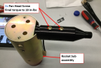
6. Remove the two pan head screws from the Rocket Attach Cone. Remove Rocket Attach Cone.
Figure 557. Rocket Housing and Rocket Attach Cone
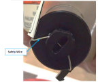
7. Safety wire the Igniter Plunger such that the plunger cannot be pulled out (away from rocket).
Figure 558. Igniter Plunger Safety Wire

8. Disconnect the electrical witness switch on the side of the Rocket Tube Assembly from the connector on the Rocket Mount. Cut cable tie, if present.(Figure 559)
Figure 559. Rocket Subassembly Electrical Harness Connection to Rocket Mount
9. Verify that the two shear screws and the pick-up collar have been removed. If not, Remove
Parachute Package
10. Remove the Rocket Mount Bracket. Retain the screws, nuts, and washers for reinstallation. (Figure 554)
a. The nuts on the inboard four AN3 bolts are inside the firewall and covered with fire barrier. Use a plastic scraper or similar tool to access the four nuts.
11. Remove the Rocket Mount with the Rocket Tube Assembly still installed.
Warning:
DO NOT point the rocket towards yourself or any other personnel.
12. Place mount on work bench on its side with the rocket pointing in a safe direction.
13. Remove the two 004042-01 1/4-20 X 3/4” screws from the bottom of the Rocket Mount Bracket. Retain the screws and any washers or other hardware for later use for installation.
Figure 560. Rocket Subassembly and Installation to Rocket Mount Bracket
Verification Method
The procedure is complete when the rocket system has been fully removed and placed in a secure location.
Parent topic