IPS Rocket Disassembly and Disposal
100772-01
Use the following to install the IPS rocket.
Applicable Aircraft Serial Numbers
All
Type of Maintenance
Line
Level of Certification
LSA-RM
Task Specific Training Required
Yes, contact ICON for rocket-specific training prior to performing any rocket-related portion of this task.
Special Tools Required
ITL00175 (Ortman Key Fixture)
Parts Required
None
Aircraft System and Number
16—ICON Parachute System (IPS)
Safety Equipment
As Needed
Consumables
None
Warning:
Do not “experiment” with the BRS Recovery System or fire it on the ground just to see if it works. People may be injured, property damaged, and thousands of dollars of expense will be incurred to repack the parachute and recharge the rocket. In addition, firing the BRS Recovery System experimentally will render it and the aircraft unusable until the factory has serviced it. Treat the BRS Recovery System like a loaded gun. Verify the “REMOVE BEFORE FLIGHT” pin is installed.
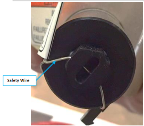
Warning:
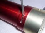
Ensure there is safety wire securing the igniter pin to igniter housing.
Figure 561. Safety Wire
Task Instructions
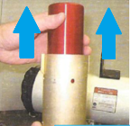
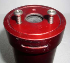
1. At the base of the rocket body/launch body there are three holes that were used to attach the rocket to the parachute. In these holes there are three 1/4-20 nylon screws. Remove these screws using a flathead screwdriver. The rocket body can now be separated from the launch body.
a. If attempted removal damages the heads of the screws, use a 11/32” or “S” size drill bit and drill through the heads of the screws, thereby releasing the launch body from the rocket body. The remaining ends of the screws will need to be removed from the rocket body.
Figure 562. Assembled Rocket
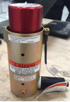
Figure 563. Base of Rocket Body with 3 Shear Screw Holes
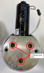
Figure 564. If Necessary, Drill Out Screw Heads
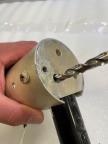
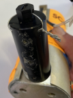
Figure 565. Slide Rocket Body Out of Launch Tube
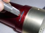
2. Using an X-acto knife or similar cutting tool, remove the silicone in the Ortman key hole located at the BOTTOM of the rocket body. See Figure 566.
Figure 566. Remove Silicone
3. Using a small screwdriver bend the end of the Ortman key out of the hole. Make sure the key is bend enough so that when the rocket body is twisted the key will be guided to the outside of the body.
Figure 567. Bend Ortman Key Out
4. Install Ortman Key Fixture (or two metal 1/4-20 bolts) into two of the shear screw holes. Clamp into figure, careful not to damage the rocket body.
Figure 568. Ortman Key Fixture or Alternate Bolts
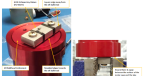
5. Inspect Ortman Key to determine which direction the case was rotated to wind key. Rotate case in opposite direction to unwind key. This may require use of an oil filter wrench or similar.
Figure 569. Winding of Ortman Key During Assembly—Rotate Opposite to Unwind

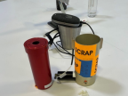
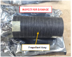
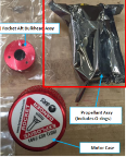
6. Remove propellant assembly and O-rings from the rocket motor case and transfer to anti-static storage bag. All other components may be discarded.
Figure 570. Disassembled Rocket Components and Storage Bag
Launch Body and Rocket Fuel Disposal
7. Follow safety precautions:
Warning:
Igniter is loud, like a small firecracker. Ensure all bystanders are aware and sufficiently protected.
◦ Wear safety glasses and hearing protection.
◦ Have fire fighting equipment standing by, i.e. fire extinguisher, shovel, garden hose, etc.
◦ Actuator takes a force of twenty pounds to activate, take care not to prematurely activate it.
◦ Treat launch body like a loaded gun.
8. Ensure that all firing and disposal of the launch body and rocket fuel is in compliance with local laws, regulations, and ordinances.
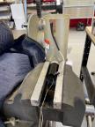
9. Place the launch body in a sturdy vise and clamp it securely, paying attention to the direction in which the body is pointed. Do not point launch tube at people or flammable objects. Take all necessary precautions to avoid fire and excessive debris.
10. Attach a long piece of wire or cable to the actuator that enables you to be a minimum of ten feet away from launch body.
Figure 571. Attach Wire Sufficient for Minimum 10ft Distance
11. Make sure everyone is clear of launch body.
12. Fire the unit. Allow launch body to cool, then discard.
13. Contact ICON for support with disposal of the anti-static bag of propellant.
Verification Method
Parent topic