IPS Rocket Subassembly
100773-01
Use the following task to assemble the IPS rocket.
Applicable Aircraft Serial Numbers
All
Type of Maintenance
Line
Level of Certification
LSA-RM
Task Specific Training Required
Yes, contact ICON for rocket-specific training prior to performing any rocket-related portion of this task.
Special Tools Required
ITL-00175 ICON Ortman Key Fixture
Parts Required
008421-01 (IGNITOR ASSEMBLY)
008416-01 (ROCKET KIT)
002102-01 (MOTOR CASE)
002268-01 (PROPELLANT)
O-ring spacers
009210-01 (AFT BULKHEAD ASSEMBLY)
Aircraft System and Number
16—ICON Parachute System (IPS)
Safety Equipment
Safety Glasses
Nitrile Gloves
Consumables
Lubricant Patch
005011-01 Silicone RTV
Warning:
Do not “experiment” with the BRS Recovery System or fire it on the ground just to see if it works. People may be injured, property damaged, and thousands of dollars of expense will be incurred to repack the parachute and recharge the rocket. In addition, firing the BRS Recovery System experimentally will render it and the aircraft unusable until the factory has serviced it. Treat the BRS Recovery System like a loaded gun. Verify the “REMOVE BEFORE FLIGHT” pin is installed into the activation handle before proceeding.
Note:
Throughout the process, take photos as required in BRS Installation Manual (020060-PM). Contact customer advocates to send photos to ICON. Steps requiring photos will be indicated.
Task Instructions
1. Locate “BRS Rocket Assembly Checklist”. (IPS Installation
Checklist)Refer to this checklist as the rocket assembly is being done. BRS rocket assembly checklist must be completed, signed, and submitted upon completion of installation.
CAUTION:
Safety glasses are required during entire rocket subassembly process.
CAUTION:
Wear gloves as necessary to prevent contamination of O-rings with debris and to prevent propellant from coming into contact with skin. Change gloves as necessary to prevent contamination of propellant with lubricant or other oils and debris.
Note:
Take photos as required. Steps requiring photos will be indicated.
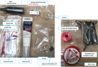
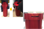
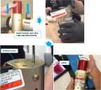
2. Obtain rocket base/igniter (launch tube) assembly and box containing rocket propellant assembly. Verify serial numbers match.
Figure 572. Example of Serial Numbers

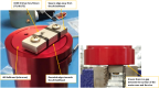
3. Open box containing rocket propellant assembly, taking care not to damage contents.
Note:
The Ortman Key Fixture provided with the rocket kit is not needed. The ICON provided tool kit contains a special Ortman Key Fixture that will be used during the assembly process.
Figure 573. Rocket Propellant Assembly Kit
4. Remove the motor case from its packaging.
CAUTION:
Do not cut into the propellant.
5. Remove the propellant assembly from its anti-static bag.
6. Inspect the propellant assembly for any damage.
7. Remove tape from ends of propellant assembly.
Note:
The propellant should be assembled with equal spacing at each end. If not, push from the shallow side until spacing is equal.
8. Inspect motor case for any debris.
9. Set one of the O-rings on top and inside of fuel liner on the propellant assembly.
a. After completing step, check-off BRS checklist R.1 Spacer O-Ring installed on top of propellant assembly.
10. Hold motor case and propellant assembly horizontal with O-ring facing the bottom of the motor case. Slide propellant assembly into motor case.
a. After completing step, check-off BRS checklist R.2 Propellant assembly loaded into rocket motor case.
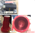
11. Orient assembly with opening facing up. Install remaining O-ring on exposed end of propellant assembly inside fuel liner.
Figure 574. Prep Bulkhead Cover for Installation
a. After completing step, check-off BRS checklist R.3 Remaining O-Rings installed in same fashion as previous.
12. Remove the aft bulkhead assembly from its plastic bag. Using the pre-soaked lubricant cloth, apply a light coating of lubricating oil to the 2x aft bulkhead O-rings.
13. Using the pre-soaked lubricant cloth, apply a light coating of lubricating oil to the inner rim of the motor case.
a. After completing step, check-off BRS checklist R.4 Bulkhead O-Rings seated correctly on bulkhead and lubed.
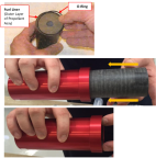
14. Align the hole in the side of the aft bulkhead with the slot on the side of the motor case. Being careful not to damage the O-rings, push the bulkhead firmly into the open end of the motor case. Resistance will be felt when the O-ring seats. Jiggle/twist the bulkhead until it loosens up, and then continue pushing until bulkhead is flush with the bottom of the motor case. The hole should now be visible in the slot.
a. After completing step, check-off BRS checklist R.5 Bulkhead installed into rocket motor case without damage to the O-Rings.
Figure 575. Install Bulkhead into Motor Case
15. Remove the Ortman key and Ortman key fixture/screws from their plastic bags.
Figure 576. Secure Motor Case in Vise
16. Inspect the ICON Ortman key fixture for sharp corners or burrs. If necessary, file down sharp edges.
17. Orient ICON Ortman key fixture (ITL-00175) so that the rounded edges of the fixutre are to the face of the aft bulkhead. Attach ICON Ortman key fixture to the aft bulkhead using the supplied screws (install in any 2 of the 3 holes in the aft bulkhead).
18. Clamp assembly into bench vise, using flat sides of the Orman key fixture. Ensure surface of motor case is not in contact with vise. If hole in aft bulkhead is not visible in slot in motor case, grasp and rotate motor case until hole appears in slot.
Note:
The ICON Orman key fixture can be clamped inside the vise.
19. Insert the short “hook” end of the Ortman key into the small hole in the aft bulkhead. Press firmly while rotating the motor case slowly towards the long end of the key (clockwise). Rotate as far as possible by hand. Some resistance is normal at the point where the bend in the key meets the end of the slot. A strap wrench may be used to help rotate the motor case.
CAUTION:
Do not mark the surface of the motor case. Do not use a pipe wrench.
Figure 577. Install Ortman Key

20. The Ortman key will be drawn up into the slot between the motor case and the aft bulkhead. Stop rotating when the tip of the Ortman key is just inside the outer wall of the motor case.
a. After completing step, check-off BRS checklist R.6 Ortman key installed into bulkhead and rocket motor case.
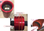
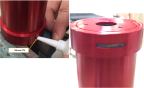
21. Fill the slot in the motor case with RTV silicone sealant and wipe flush with surface.
a. After completing step, check-off BRS checklist R.7 Ortman key slot in rocket motor case filled with silicone sealant.
Figure 578. Fill Slot with RTV Silicone
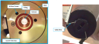
22. Inspect launch tube assembly for any signs of damage from shipment. Check the following:
◦ foil seal intact
◦ base surface clean
◦ O-ring lubricated and seated in grooved recess
◦ 3x nylon shear screws installed loose in the base
◦ Inside of launch tube is free of debris or packing materials
◦ Safety wire is installed through actuator in end of igniter assembly
a. After completing step, check-off BRS checklist R.8 Base O-Ring seated correctly onto base and lubed.
Figure 579. Inspect Launch Tube Assembly
Note:
Orient the rocket into the housing so that the labels on the rocket and on the housing are as close together as possible.
23. With launch tube assembly facing upwards, carefully insert fueled motor case into launch tube assembly. Holding both together, rotate assembly so the motor case points downward.
24. Remove tape covering 3x shear screw heads (if present).
Note:
Start all 3 screws used in Step 26 before tightening any of them. Screws are plastic. Be careful not to cross thread or over tighten them. If screws do not go in easily, back them out and try again.
25. Using flathead screwdriver, carefully thread the 3x pre installed shear screws located in the base into the corresponding holes in the motor case. Torque screws to 3.0 ± 0.5 in-lbs.
a. After completing step, check-off BRS checklist R.9 Loaded rocket body attached securely to base w/ 3 Nylon shear screws (Torque 3.0 ± 0.5 in-lbs.)
Note:
BRS Checklist R.10 will be checked off in Parachute/Rocket Install. IPS Rocket Installation
26. Take Photo(s) of the rocket fully assembled. Ensure that the serial number and expiration date of the rocket is included in the pictures.

27. If not proceeding directly with rocket installation in aircraft, store subassembly in explosives storage cabinet.
Verification Method:
Ensure the rocket is properly assembled, all required photos have been taken, and BRS Checklist have been marked complete. Photos and checklists shall be sent to ICON Aircraft upon completion.
Parent topic