Install Parachute Package
100448-01
Use the following to install the parachute installation.
Applicable Aircraft Serial Numbers
All
Type of Maintenance
Line
Level of Certification
LSA-RM
Task Specific Training Required
Yes, contact ICON for rocket-specific training prior to performing any rocket-related portion of this task.
Special Tools Required
None
Parts Required
004025-01 (BRS CABLE TIES)
Aircraft System and Number
16—ICON Parachute System (IPS)
Safety Equipment
As Needed
Consumables
Isopropyl Alcohol
Loctite 242
ICA012079 (Torque Stripe)
Note:
Throughout the process, take photos as required in BRS Installation Manual (020060-PM). Contact customer advocates to send photos to ICON. Steps requiring photos will be indicated.
Task Instructions
2. Inspect and clear parachute chamber of FOD.
3. Reinstall parachute into parachute bay.
4. Route the Velcro retaining straps through the four retaining strap brackets. (Take Photo.)
5. Install parachute bridle (harness) to the large quick link. During removal, temporary zip ties and/or labels may have been used to mark harness “C” ends for reinstallation. Once the harness is reinstalled, remove these zip ties and/or labels.
a. Clean quick link with isopropyl alcohol, allow to dry fully.
b. Apply Loctite 242 to quick link threads.
c. Torque link to 240 in-lbs.
d. Clean exterior surface with isopropyl alcohol and apply torque stripe.
e. Take Photo of the deployment bag and three harnesses secured in the torqued quick link (with one torque stripe applied).
6. The packed parachute is sent from the BRS facilities with pin tether and/or curved release pins installed secure in a grommet and loop. If release pin tether and/or curved release pins have been removed during installation, they will need to be reinstalled and secured.
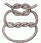
a. Secure pins with “2 and 1 knot” using Type 2 Glazed, 4 ply thread. The “2 and 1 knot” is a “surgeons knot” with two additional “overhand knots” in opposing directions, for added security. (Figure 535)
b. Perform the “surgeons knot”, pull taut, then make an “overhand knot” in the opposite direction, pull taut; then make a second “overhand knot” in the opposite direction to the first “overhand knot”. Pull taut. (Figure 536)
c. Take Photo of the fully installed parachute, ensuring the large quick link is visible with torque stripe down.
Figure 535. Curved Release Pin with Tether
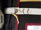
Figure 536. 2 and 1 Knot Securing Curved Release Pin
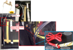
7. Route the rocket lanyard (already attached to the deployment bag) along side of the rocket assembly to determine the required length of lanyard. The rocket lanyard MUST NOT be routed under any other harness or structure. Once the required length of lanyard is determined, the remaining length should be “looped” (without knotting) and secured using 2x small BRS cable ties (PN-004025-01), so that they can be neatly stowed. Ensure that only BRS zip ties are used to secure the rocket lanyard. Ensure the opposite end of the incremental harness is connected to the deployment bag with a lark’s head knot. Secure rocket collar lanyard and incremental harness under the left side flap of the deployment bag (Take Photo.), using installed Velcro fasteners at the top side of the deployment bag.
8. See Landing
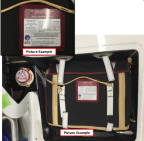
Gear IPS Interface Test. Take a close-up Photo of the parachute serial number and date(s). Take Photo of the completed parachute/rocket system.
Figure 537. Picture Examples

Verification Method:
Verify all required photos have been taken and BRS Checklist PS.4-8, PS.13-14 items have been marked complete. (IPS Installation
Checklist) Photos and checklist shall be sent to ICON upon completion.
Parent topic