Install Nose Landing Gear Actuator
100359-01
Use the following task to remove the Nose Landing Gear (NLG) Actuator.
Applicable Aircraft Serial Number
All
Type of Maintenance
Line
Level of Certification
A&P
Task Specific Training Required
No
Special Tools Required
None
Parts Required
ME001203 (NOSE LANDING GEAR ACTUATOR)
AN4C10A (BOLT, MACH, CRES, .250-28X.563)
NAS1149C0432R (WASHER, FLAT, CRES, .250X.032XPSVT)
ICA008136 (BUSHING, PLAIN, CRES, .250X.032XPSVT)
119255 (BOOT, ACTUATOR)
LARGE CLAMP (30-45/9-W5, WORM DRIVE, NORMA TORRO, .35X1.19-1.75)
SMALL CLAMP (3808, WORM DRIVE, MINI, .312X0.906)
2X MS21043-08 (NUT, SLFLKG, RDC HEX, CRES, 8-32)
2X NAS1149CN832R (WASHER, FLAT, CRES #8X.032, PSVT)
2X NAS1149C0332R (WASHER, FLAT, CRES, .203X.032, PSVT)
2X MS21043-3 (LOCKING NUT, 10-32)
Aircraft System and Number
11—Landing Gear
Safety Equipment
As Needed
Consumables
Tef-Gel®
Task Instructions
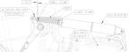
1. Slide NLG Actuator into the NLG box and attach the aft end of the actuator to the NLG box bracket using the BOLT, WASHER, MS21032-4 nut, and BUSHING. Torque bolt to 48 in-lbs.
2. Allow approximately .05" of BOOT to protrude beyond the clamp then Slide NLG Actuator BOOT over the NLG actuator rod end and secure with a LARGE CLAMP and SMALL CLAMP.
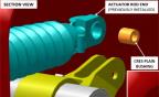
Figure 390. Boot Installation
3. Secure the AFT end of the BOOT over the NLG box flange. Position the BOOT so that it is as close to the NLG box as possible. Torque LARGE CLAMP until there is a rise in torque then 1/4 turn more.
4. Verify Boot is not twisted and continue to position the FWD end of the boot on the rod end as close to the end of the rod as possible. Torque SMALL CLAMP until there is a rise in torque then 1/4 turn more.
5. Insert BUSHING into the bearing and connect the rod end to the NLG bell crank using the BOLT and WASHER. Apply Tef-Gel® to BUSHING and BOLT threads and shank prior to assembly. Torque bolt to 53 in-lbs.
Figure 391. Actuator Detailed View
6. Secure the new limit switch bracket assembly to the studs:
a. Using isopropyl alcohol, clean surfaces where lubricant will be applied.
b. Apply ICA012078 Tef-Gel to the threads of the studs.
c. Install limit switch assembly onto studs with 2x NAS1149CN832R washers and 2x MS21043-08 nuts torqued to 14 in-lbs (if 8-32 studs were used), or with 2x NAS1149C0332R washers and 2x MS21043-3 nuts torqued to 20 in-lbs (if 10-32 studs were used).
Figure 392. Installed Limit Switch Subassembly
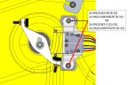
Note:
The 1.0 configuration is oriented 90° from shown in Figure 392.
7. Connect NLG actuator electrically to D9024P of the FWD Fuselage Wire Harness.
Verification Method
Rig the actuator. Nose
Landing Gear (NLG) Rigging and Check with Landing Gear Down (1.0
Configuration)Nose
Landing Gear (NLG) Rigging and Check with Landing Gear Down (1.2
Configuration)
Parent topic