Nose Gear Inspection
100304-01
Inspect the nose landing gear system.
Applicable Aircraft Serial Numbers
All
Type of Maintenance
Line
Level of Certification
LSA-RM
Task Specific Training Required
No
Special Tools Required
Wing Jack Point Adapter—ICA009750
Parts Required
None
Aircraft System and Number
11—Landing Gear
Safety Equipment
As Needed
Consumables
None
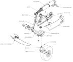
Figure 386. Nose landing gear assembly detail.
Task Instructions
a. Remove the main landing gear 15A fuse from the overhead console. Save this fuse.
b. Remove the instrument panel top(s). (See G3X Instrument Panel Top Panel Removal, Right
Instrument Panel Top Panel Removal/Left
Instrument Panel Top Panel Removal.)
c. Fold the wings of the aircraft. This will move the center of gravity aft so that it is easier to lift the nose up and down during the NLG rigging checks.
d. Connect battery charger to the charging terminals. The charger used must have a selectable Lithium charging mode.
e. Have a foam block or equivalent nearby that can be placed under the aircraft on the keel aft of the NLG wheel well that will allow the nose wheel of the aircraft to have approximately one inch or more clearance from the ground. This block will need to be removed numerous times during the procedure.
2. Check for attachment.
a. After the aircraft has been jacked, apply an alternating force to the nose landing gear and validate that there is not excessive play or travel in the system.
b. After the aircraft has been jacked, apply 10-15 lbs of alternating force to the nose landing gear to confirm all components are attached and secure.
3. Verify that all attachment hardware is correctly installed, refer to Figure 386 for hardware location.
4. Validate that the difference between the forward and aft bellcrank positions is 1.5°
a. With the weight off the nose landing gear, gently rotate the NLG bellcrank forward with moderate hand pressure. Measure the angle with a digital protractor. (See Figure 387) Record measurement.
b. With the weight off the nose landing gear, gently rotate the NLG bellcrank backward with moderate hand pressure. Measure the angle with a digital protractor, taking care to take the measurement in the same location as before. Record measurement.
c. If the measured difference is greater than 1.5°, the actuator, and all mounting hardware (bushings, bolts, etc), must be replaced. (Install
Nose Landing Gear Actuator.)
Figure 387. Digital Protractor
5. Evaluate the nose landing gear doors for smooth operation and excessive play.
a. With the landing gear in the extended position, first apply an alternating side load to both the left hand and right hand nose doors. There should be no extensive play, as the doors are locked in this position.
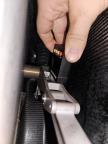
b. Reach inside the nose cavity and override the door forks (shown in illustration) by rotating them clockwise (left hand fork) and counter clockwise (right hand fork). This will override the locking mechanism and allow the user to evaluate the door operation for smoothness, as well as play in the mechanical linkages.
6. Inspect the nose door for attachment and rigidity.
a. Apply a side pressure to the nose landing gear door and examine the bond line between the door and its respective bonded bracket. There should be no gapping or delamination between the door and bracket.
7. Visually inspect the nose gear boot for wear and tear or poor seal.
8. Inspect nose landing gear for cracks or any other forms of significant wear.
9. Cycle the landing gear several times, verifying correct function of the following:
a. Nose gear doors close fully against the fuselage skins with no gaps or looseness.
b. There are uniform gaps between the edges of the doors and the fuselage joggle.
c. The door flanges rest against each other.
d. Instrument panel position lights indicate correctly.
e. Normal gear function with no blown fuses.
Verification Method
Verify that each check is passed successfully.
Parent topic