Install Engine Cowlings
100335-03
Use the following instructions to install top engine cowl, fan shrouds, and exhaust fairings.
Applicable Aircraft Serial Numbers
All
Type of Maintenance
Line
Level of Certification
Owner/Pilot
Task Specific Training Required
No
Special Tools Required
None
Parts Required
None
Aircraft System and Number
08—Fuselage and Vertical Tail
Safety Equipment
As Needed
Consumables
ICA012078 (LUBRICANT, GENERAL PURPOSE) Tef-Gel®
Task Instructions
a. Apply LUBRICANT and install one countersunk screw with a #15 Torx driver.
b. Apply LUBRICANT and install three #10-32 button head screws with #20 Torx driver.
c. Torque to 26 in-lb.
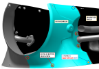
Figure 216. LH Fan Shroud Installation

a. Apply LUBRICANT and install two countersunk screws with a #15 Torx driver.
b. Apply LUBRICANT and install four #10-32 button head screws with #20 driver.
c. Torque to 26 in-lb.
Figure 217. RH Fan Shroud Installation
3. Install the LH and RH muffler fairing with nine button head screws using a #20 Torx driver. Apply LUBRICANT and torque to 26 in-lb.
4. Position the top engine cowl over the engine and connect the ELT and transponder coax connectors.
a. Transponder - D9008J2
b. ELT - D9103J
c. G3X ADS-B - D9156J (G3X configuration only.)
5. Use a #15 Torx driver to secure the top engine cowl with 16 1/4-turn fasteners.
Verification Method
The task is complete when all engine cowlings and exhaust fairings have been installed.
For Aera 796 aircraft, see Verification Method steps 1 and 4 from Install
ADS-B GPS Antenna for GPS system.
For G3X aircraft, see Verification Method from Install
G3X ADS-B Antenna for GPS system.
Perform ELT unit self-test according to SELF TESTS of Section 9 of ACK Technologies Inc. Model E-04 ELT Installation/Operation Manual, or ELT Battery
Self Test
Note:
Reference SAFO 17002 as needed within performing transponder maintenance tasks.
For Aera 796 aircraft, perform a transponder functional test for transmission on 121.5 MHz and 406 MHz. If the control unit was replaced, configure the transponder. See 00560-00-AQ--TRiG TT21/TT22 Mode S Transponder Installation Manual.
For G3X aircraft, perform a transponder functional test for transmission on 121.5 MHz and 406 MHz. If the control unit was replaced, configure the transponder. See 190-01499-10 Garmin GTX 34R/45R Installation Manual and 190-01115-01 Garmin G3X/G3X Touch Installation Manual.
Parent topic