Inspect Throttle Control for Proper Travel and Security
100315-02
Use the following to inspect throttle control for proper travel and security. Perform the inspection with a second person.
Applicable Aircraft Serial Numbers
All
Type of Maintenance
Line
Level of Certification
LSA-RM
Task Specific Training Required
No
Special Tools Required
Second person
Parts Required
None
Aircraft System and Number
13—Propulsion
Safety Equipment
As Needed
Consumables
LOCTITE 220
LOCTITE 243 (THREADLOCKER, PRIMERLES, OIL TOL, REMOVABLE MED STR, BLUE)
Task Instructions
1. Remove engine cowling. (Remove
Engine Cowlings) It is necessary to access the engine throttle lever inside the cockpit and the cable lever on the engine. (Figure 422)
Figure 422. Throttle Assembly

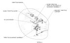
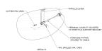
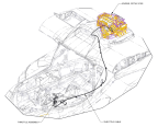
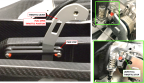
Figure 423. Throttle Assembly—Exploded View.
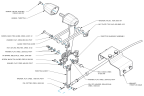
Note:
ASN 00049 and below use a different THROTTLE CABLE BRACKET than shown.
3. Have a helper in the cockpit move the throttle forward and backward to confirm if the cable is clear and free to move.
4. Check that the throttle cable is secured and connected appropriately to throttle lever. (Figure 423 Figure 428)
5. Clear and remove any obstructions that would prevent cable from moving.
6. Check in the idle position that the throttle lever has at least 0.50 inches of clearance to full travel.
a. In cockpit, retract throttle handle to contact AFT stop (idle position). At engine, ensure lever idle stop contacts idle adjustment screw at the same time or just before the throttle handle contacts the aft stop. (Figure 424)
Figure 424. Idle Position Adjustment
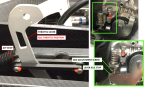
Figure 425. Full Throttle Position Adjustment
a. If the new throttle body housing is installed, perform the idle adjustments using the Secondary Idle Adjustment Screw as shown in Figure 426. The Secondary Idle Adjustment Screw is identified by the spring. This screw requires no thread locking compound when idle adjustment is completed. NOTE: Heat gun is not needed for new throttle body.
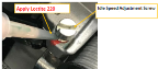
b. If the old throttle body housing is installed, use a heat gun at approximately 250°F to loosen idle speed set screw (previously installed with Loctite). Once adjusted and idle set is complete, using isopropyl alcohol, clean surfaces where Loctite 220 will be applied. Apply wicking Loctite 220 to the idle speed adjustment screw threads (Figure 427). Clean up excess threadlocker.
Figure 426. Secondary Idle Adjustment Screw
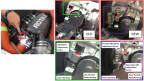
Figure 427. Loctite 220 Placement
8. Check in the full throttle position that the throttle lever has at least .050 inches clearance.
◦ In cockpit, move throttle handle to full throttle position (FWD stop). At engine, ensure the lever full throttle stop contacts the throttle body before the throttle handle contracts the FWD stop. (Figure 425)
Note:
The throttle lever on the engine is spring loaded to the full open position.
Figure 428. Throttle Fixation Fastener and Jam Nut
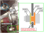
10. When cable adjustment is complete, torque jam nut to 45±5 in-lb.
11. When cable adjustment is complete, torque cable fixation fastener to 35±5 in-lb. Check that hardware is secure.
Verification Method
Verify that all checks listed above are within acceptable limits. If full travel not able to be obtained, contact ICON owner support.
Parent topic