Landing Gear Actuator Reed Switch Adjustment Procedure (Thumb Wheel Design)
100392-02
There are multiple configurations of actuators in the fleet currently. Please use applicable actuator part number and Figure 356 to identify whether this section is applicable to your aircraft actuator. If your actuator doesn’t match this part number/configuration refer to Landing Gear
Actuator Reed Switch Adjustment Procedure (Threaded Rod Design). Use this procedure to adjust the limit switch on the desired actuator.
Applicable Actuator Part Number
ICA013160
ICA013161
Type of Maintenance
Line
Level of Certification
LSA-RM
Task Specific Training Required
No
Special Tools Required
None
Parts Required
None
Aircraft System and Number
11—Landing Gear
Safety Equipment
As Needed
Consumables
None
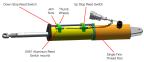
Figure 356. Landing Gear Actuator for ASN 00110+
Task Instructions
1. Unless already performed, remove any interior panels needed to gain access to the actuator. (Right
Instrument Panel Top Panel Removal)(Removal
and Installation of Inspection Panels and Fairings)
a. Remove the main landing gear 15A fuse from the overhead console. Save this fuse.
b. Remove the instrument panel top(s). (See G3X Instrument Panel Top Panel Removal, Right
Instrument Panel Top Panel Removal/Left
Instrument Panel Top Panel Removal.)
c. Fold the wings of the aircraft. This will move the center of gravity aft so that it is easier to lift the nose up and down during the NLG rigging checks.
d. Connect battery charger to the charging terminals. The charger used must have a selectable Lithium charging mode.
e. Partially extend/retract the landing gear.
f. Have a foam block or equivalent nearby that can be placed under the aircraft on the keel aft of the NLG wheel well that will allow the nose wheel of the aircraft to have approximately one inch or more clearance from the ground. This block will need to be removed numerous times during the procedure.
3. Use an open-end wrench to loosen the jam nut tightened against the limit switch adjustment saddle for the affected switch.
4. Use the thumb wheel to set the affected switch to the desired position.
5. Torque the jam nut to 20-24 in-lbs to secure the position of the limit switch.
6. Power up the aircraft, and actuate the landing gear to verify adjustment.
7. Repeat steps 3 thru 5 as needed until the landing gear is properly adjusted.
8. Replace the interior panels, extend the landing gear, and lower the aircraft off the jacks. (Right
Instrument Panel Top Panel Installation)(Removal
and Installation of Inspection Panels and Fairings)
Verification Method
Power up the aircraft, and actuate the landing gear to verify adjustment.
Parent topic