Install Insulation on Muffler Shield
100889-00
Use the following procedure to install the full insulation on the Muffler Shield.
Applicable Aircraft Serial Numbers
All
Type of Maintenance
Line
Level of Certification
LSA-RM
Task Specific Training Required
No
Special Tools Required
Grommet Punch
Parts Required
See IPC Reference
Aircraft System and Number
08—Fuselage and Vertical Tail
Safety Equipment
As Needed
Consumables
ICA012078 (LUBRICANT, GENERAL PURPOSE ) Tef-Gel
AC-111 (ADHESION PROMOTOR, AC-111)
82180 (ADHESIVE, SILICONE, GASKET MAKER, BLACK)
TT-I-735A or equivalent (ISOPROPYL ALCOHOL)
IPC Reference
Task Instructions
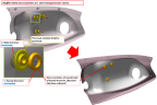
1. Prepare insulation and muffler.
a. If required, trim insulation to fit muffler shield. Ensure hat the insulation is cut to adequately cover the muffler clearance depression. The insulation must terminate between the inner and outer tangencies of the radius that defines the depression.
b. Scuff surface of muffler shield with Scotchbrite to remove surface gloss. Wipe with isopropyl alcohol. Dry using lint-free cloth and let stand for 15 minutes.
c. Apply AC-111 adhesion promotor on the area where insulation will be installed; let it dry for two minutes.
2. Install insulation. (Figure 222) Install precut insulation material by centering into contour of cowling muffler shield and smoothing out to the edges.
a. Remove backing before installation. Minimally handle adhesive side of insulation and apply firm pressure when applying insulation to ensure insulation does not lift off the carbon surface.
b. It is acceptable to dart (cut slits in the insulation to allow it to fit into radius) and trim excess material to achieve a fit that will cover cowl muffler.
c. The maximum allowable gap in part coverage is 0.062 inch.
d. Place insulation within ± .25 inch of radius tangentially of muffler shield.
Figure 222. Insulation Application
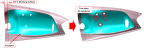
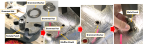
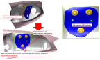
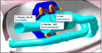
Figure 223. Fabric Grommets One and Two
b. Place the Muffler Shield over the washer. Ensure shield is sitting flush on the male side of the insertion tool.
c. Insert the grommet hat into the male side of the insertion tool.
d. Place the female side of the installation punch over the fabric grommet. Press grommets into place.
Figure 224. Installation of Fabric Grommets One and Two

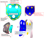
Figure 225. Fabric Grommet Three
b. Place the Muffler Shield over the hat. Ensure the shield is sitting flush on the female side of the insertion tool.
c. Place the washer of the fabric grommet on the Muffler Shield centered at the protruding grommet hat.
d. Place the male side of the installation punch over the fabric grommet. Press grommets into place.
Figure 226. Installation of Fabric Grommet Three
6. Install the male and female silicone grommets. (Figure 227) Note the orientation of the grommets.
Figure 227. Installation of Silicone Grommets
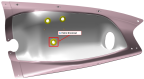
7. Orient Heatshield Assembly (Figure 228) and align 2x aluminum grommet holes in heatshield with 2x holes in muffler shield. Hold heatshield in place and verify there is a minimum clearance of .125 inches between the edge of all the silicone grommets (3x) and heatshield.
a. If clearance is less than .125 inches, trim heatshield cutout to achieve required clearance. Remove any sharp edges.
b. Bend the heatshield to conform to the shape of the muffler shield.
Figure 228. Heatshield Assembly Location
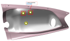
8. Remote heatshield from muffler shield and orient with INBD side facing up. (Figure 229) Prepare for installation.
a. Using isopropyl alcohol, clean both mating surfaces (insulation and heartshield) where adhesive will be applied.
b. Apply black silicone adhesive in 11x locations shown, approximately .125-.250 inches from the perimeter edge. Beads shall be .100-.300 inches in width and .700-1.300 inches in length.
c. Carefully flip over heatshield with adhesive and install onto muffler shield so that adhesive side is facing muffler shield and holes are aligned.
9. Secure the Heatshield Assembly using the noted hardware:
a. Using isopropyl alcohol, clean surfaces where lubricant will be applied.
b. Apply lubricant (ICA012078) liberally to threads and shank of screws. Secure heatshield to muffler shield using screws and washers. (Figure 229)
c. Torque screws to 13 in-lbs. Verify torque on each screw to ensure heatshield and insulation material are compressed sufficiently. Ensure at least one full thread is protruding from each nutplate.
d. Allow adhesive to cure. Ensure heatshield edges do not lift up.
e. Ensure there is no squeeze out around perimeter of heatshield.
Figure 229. Install Heatshield
10. Install exhaust assemlby. (Figure 230 and Figure 231) Ensure the muffler assembly is oriented properly with the dimple in the clamp. Install nus; final torque will be completed later.
Note:
Do not reuse lock nuts if the threads or locking features are damaged.
Figure 230. Exhaust Clamp Hardware, Outbound View
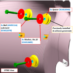
Figure 231. Exhaust Clamp Hardware, Inbound View
12. Torque the three nuts on the exhaust clamp to 20-22 in-lbs.
Verification Method
The task is complete when the exhaust components have been reinstalled and the exhaust clamp nuts have been torqued to 20-22 in-lbs.
Parent topic