Landing Gear Limit Switch Adjustment Procedure (Mechanical Switch Design)
100846-00
There are multiple configurations of actuators in the fleet currently. Please use the applicable actuator part number to identify whether this section is applicable to your aircraft actuator. Use this procedure to adjust the limit switch on the desired actuator.
Applicable Actuator Part Number
ME001203 (NLG)
ME001169 (MLG)
Type of Maintenance
Line
Level of Certification
LSA-RM
Task Specific Training Required
No
Special Tools Required
None
Parts Required
None
Aircraft System and Number
11—Landing Gear
Safety Equipment
As Needed
Consumables
None
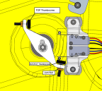
Figure 357. MLG Limit Switch Adjustment

Figure 358. NLG Limit Switch Adjustment
Task Instructions
1. Unless already performed, remove any interior panels needed to gain access to the actuator. (Right
Instrument Panel Top Panel Removal)(Removal
and Installation of Inspection Panels and Fairings)
3. If adjustment of the extended position is necessary, adjust rigging by loosening jam nut and adjusting thumbscrew (ICA016069).
a. Partially extend/retract the landing gear.
b. Loosen the jam on the stop bolt/thumbscrew
c. Adjust the stop bolt/thumbscrew in or out as required.
d. Hold the head of the stop bolt/thumbscrew and carefully torque the jam nut to 13-17 in-lbs.
e. Repeat as necessary to achieve rig (see Related Tasks).
4. Replace the interior panels, extend the landing gear, and lower the aircraft off the jacks. (Right
Instrument Panel Top Panel Installation)(Removal
and Installation of Inspection Panels and Fairings)
Verification Method
Power up the aircraft, and actuate the landing gear to verify adjustment.
Parent topic