Install 1.2 Pedal Adjustment Gas Strut
100806-00
Use this task to install the 1.2 style pedal adjustment gas strut.
Applicable Aircraft Serial Numbers
00012, 00021+
Type of Maintenance
Line
Level of Certification
LSA-RM
Task Specific Training Required
No
Special Tools Required
None
Parts Required
ICA011684 (GAS STRUT, LOCKING RUDDER, CYLINDER, 5.7IN, 25LB, 5MM PIN)
Aircraft System and Number
06—Flight Controls
Safety Equipment
As Needed
Consumables
ICA012078 (LUBRICANT, GENERAL PURPOSE)
LOCTITE 243 (THREADLOCKER, PRIMERLESS, OIL TOL, REMOVABLE MED STR BLUE)
Task Instructions
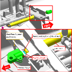
1. Apply ICA012078 lubricant liberally to threads of the release head and the forward jam nut.
a. Position gas strut between floor support and mounting bracket on rudder pedal carriage.
b. Thread release head onto gas strut until the release head lever is at full fwd rotation. Do not exceed 10 in-lbs torque on the release head while clocking the release lever.
c. Align the release head couple slot with the cable thru slot.
Figure 172. Align the Release Head
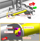
d. Tighten the gas spring jam nut (fwd nut, included with gas strut) against the fwd floor support. Torque jam nut to 22-25 in-lbs. See Figure 171.
e. Apply LOCTITE 243 to adjustment gas strut aft threads. Compress pedal adjustment gas strut slightly and insert thread into gas strut bracket. Using protective material and pliers, secure body of adjustment gas strut from rotating and install nut securing gas strut to strut bracket. Torque nut to 25-30 in-lbs. See Figure 173.
Figure 173. Torque Stripe Location
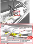
a. Feed cable end fitting through slot in floor support.
b. Seat the cable end fitting into the release head and the cable end into the release lever as shown.
Figure 174. Rudder Release Cable
4. Install forward pedal closeout panel and hardware using ICA012078 lubricant. Torque to 7-10 in-lbs.
6. If removed, reinstall IP top. See Right
Instrument Panel Top Panel Installation, Left
Instrument Panel Top Panel Installation, and G3X Instrument Panel Top Panel Installation
Verification Method
Verify pedals adjust properly.
Parent topic