Replace 1/4-Turn Fastener Receptacles
100892-00
Use the following procedure to replace the captive fasteners on the engine cowl, lower cowl, or muffler shield.
Applicable Aircraft Serial Numbers
All
Type of Maintenance
Line
Level of Certification
LSA-RM
Task Specific Training Required
No
Special Tools Required
None
Parts Required
See IPC Reference
Aircraft System and Number
08—Fuselage and Vertical Tail
Safety Equipment
As Needed
Consumables
ICA012078 (LUBRICANT, GENERAL PURPOSE) Tef-Gel
AC-111 (ADHESION PROMOTOR, AC-111)
TT-I-735A or equivalent (ISOPROPYL ALCOHOL)
IPC Reference
Task Instructions
2. If the receptacle is damaged, carefully drill out the rivets securing the affected receptacle.
3. With a bit, carefully deburr and clean the holes.
CAUTION:
Do not elongate the holes further. If the holes are oversized, contact ICON for assistance.
4. Install the new receptacle with appropriate length blind rivets, ensuring the black tab is visible on the receptacle.
Note:
Ensure that the locking clip groove on the receptacle is facing outward/upward for ease of access.
Note:
Do not remove the black tab until the fastener has a proper fit. If there is no black tab on the receptacle, then use a pick tool to pry locking clip out of the groove in the receptacle barrel surface.
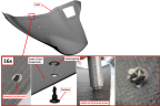
Figure 233. Receptacle Installation

5. Install ¼-turn fastener into the part and test fit part fasteners over receptacles.
Note:
Do not install retainers now. (Figure 234)
Figure 234. Fastener Installation
6. Position part. Lock fastener and continue to turn fastener, adjusting receptacle inserts until the faster is set to the proper locked height.
7. Unlock fastener (quick push-turn motion) and remove part. Remove the black tab, if present, to snap the clip back into the locking groove.
8. Turn insert ½ turn maximum to snap the clip into the locking groove and confirm the insert is locked in position.
9. Install press-on retainers on the fastener. Support opposite face of part while pressing on the retaining rings. (Figure 234)
10. Reinstall part.
Verification Method
The ¼ turn fastener can be properly installed into the receptacle.
Parent topic