Inspect Roll Cable Tension
100030-00
This section contains instructions to check roll cables for correct tensions.
Applicable Aircraft Serial Numbers
All
Type of Maintenance
Line
Level of Certification
LSA-RM
Task Specific Training Required
No
Special Tools Required
Tensiometer and Operating Instructions
1 x DIA .250 Rig Pin
5 x DIA .1875 Rig Pins
Parts Required
None
Aircraft System and Number
06—Flight Controls
Safety Equipment
As Needed
Consumables
None
Task Instructions
1. Remove left hand and right hand forward and main cockpit floor boards. (Remove
Cockpit Floorboard)(Remove Cockpit Floorboard)
2. Remove seat back and seat pan, if required. (Remove Seat Back)(Seat Pan Removal) Retain all fastening hardware.
4. Remove seatbelt cover, left hand and right hand baggage sidewalls, and baggage headliner. (Baggage Sidewall Panel Removal Baggage Sidewall Panel Removal) (Removal
and Installation of Inspection Panels and Fairings) (Remove Seat Back) If headliner cannot be removed without removal of overhead console, removal is permitted.
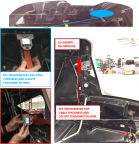
Figure 101. Pitch Sector Rig Pin Location

Figure 102. Control Stick Rig Pin Location

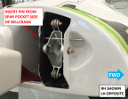
7. Fold both aircraft wings and install a .1875in diameter rig pins at both of the wing socket bellcrank. Figure 103
Figure 103. Wing Socket Bellcrank Rig Pin Location
8. Use the tensiometer (upper cable thickness = 3/32 in, LH and RH fuselage cable thickness = 1/8 in) to measure roll cable tension at locations specified in, see Figure 104. Ensure they all are within 25-30 lb of tension. Refer to the manufacturers’ calibration card to correctly read cable tension for the cable diameter.
Figure 104. Tensiometer Locations
9. Remove all installed rig pins:
a. 2X Wing socket bellcrank rig pins
b. Control stick rig pin
c. FWD pitch sector rig pin
10. Install seatbelt reel cover, left hand and right hand baggage sidewalls, and baggage headliner. If the overhead console was removed, re-install. (Seat Belt Inertia Reel Installation) (Baggage Sidewall Panel Installation Baggage Sidewall Panel Installation) (Headliner Installation) (Removal
and Installation of Inspection Panels and Fairings)
11. Install baggage floor boards using hardware retained during removal. (Baggage Floor Installation)
12. Install seat back and seat pan using hardware retained during removal, if required. (Install
Seat Back) (Seat Pan Installation)
Verification Method
Record results and check against requirement. If requirement is not met complete aileron rigging. (Rigging
Roll Controls)
Parent topic