Install Bridle Clamp, Roll
100893-00
Use the following when performing the initial rigging for a new cable in the Autopilot Configuration. To be completed between Step 10 and 11 of Rigging
Roll Controls.
Applicable Aircraft Serial Numbers
00139+ (Autopilot Configuration Only)
Type of Maintenance
Line
Level of Certification
A&P
Task Specific Training Required
No
Special Tools Required
ITL015538 (CRANK ARM POSITIONING FIXTURE)
Parts Required
4x NAS1149C03324 (WASHER, FLAT, CRES, #8, .032)
4x AN3C4A (BOLT, MACH, CRES, 10-32X.125)
Aircraft System and Number
06—Flight Controls
Safety Equipment
As Needed
Consumables
ICA012078 (LUBRICANT, GENERAL PURPOSE)
ICA012079 (INSPECTORS LAQUER, ANTI SABOTAGE, ORANGE) Torque Stripe
TT-I-735A or equivalent (ISOPROPYL ALCOHOL)
Task Instructions
1. Loosen the nut from the cable clamps on the roll servo subassembly and slide the cable clamps apart from each other.
Figure 114. Cable Clamps Reference
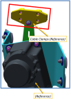
Figure 115. Bridle Clamp with Torque Value

2. Slide the control cable between the loose cable clamps and fit into the control cable slot.
3. Torque the nut to 11.1-13.1 in-lb. Ensure at least one full thread is protruding from the nut.
Note:
Ensure the control cable is in the slot and not being pinched by the clamps.
4. Using isopropyl alcohol, clean surfaces where lubricant will be applied.
5. Apply lubricant liberally to threads and shank of bolts.
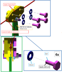
6. Install 4x washers and 4x bolts into the cable clamps until the bolt and washer contacts the face of the cable clamp.
Note:
Ensure the bolts are contacting the clamp face and the control cable is not pinched.
Figure 116. Install Washers and Bolts
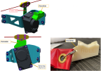
7. Insert the crank arm positioning fixture (ITL015538) labeled "ROLL" between the servo and the cable clamps. The crank arm should be in the correct position.
Note:
In the correct position, the crank arm will lock into place with the positioning fixture.
Figure 117. Servo Assy and Fixture
8. Evenly tighten the 4x bolts ¼ - ½ turn each in a criss cross pattern (1-2-3-4) until the clamps are snug around the cable and prevent the cable from moving freely.
Figure 118. Tighten Bolts

9. Using isoproply alcohol, clean surfaces where inspector's lacquer (torque stripe) will be applied.
10. Apply torque stripe to cable and clamp.
11. Remove the crank arm positioning fixture, rig pins, and safety wire on the control cables from the roll system.
Figure 119. Remove Fixture and Roll the Aircraft
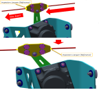
12. Roll the aircraft to the right so that the cable and cable clamps move and provide access for the final torque. Use the torque stripe as a guide to ensure the cable hasn't slipped through the cable clamps.
13. Use the hex feature on the backside of the cable clamp to prevent the clamps from rotating while torquing the bolts ¼ - ½ turn each in a criss cross pattern (1-2-3-4) until torqued to 33-35 in-lb.
Figure 120. Rear View

14. Using isopropyl alcohol, clean surfaces where torque stripe will be applied. Apply torque stripe to protruding threads, across the nut, washer, and onto the adjacent structure for the 1x shoulder stripe. Apply torque stripe to the bolt head, across the washer, and onto the adjacent structure for the 4x hex bolt heads on the cable clamps.
Figure 121. Final Torque Stripe

Verification Method
Verify that the torque stripe has not been broken and cable has not slipped in clamps. Verify that the bearing from the roll servo assembly rotates freely and the cable clamps and crank arm do not contact.
Parent topic